
Processing Workflow
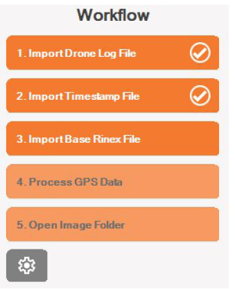
Follow the workflow steps located on the left-hand panel to process your drone’s mission data.
Each step in the workflow is marked by a progress indicator. When a step is successfully completed, a tick appears beside it to confirm completion. Steps that are greyed out are disabled until one or more prerequisite actions are satisfied.
The button located beneath the workflow steps allows you to define PPK processing preferences.
Step 1: Import Drone Log File
Use this step to load your drone’s mission log.
1. Click Import Drone Log File.
2. Browse to your mission folder and locate the log file.
3. Supported file formats include:
• .bin (preferred)
• .rtk (preferred)
• .obs
• .dat
4. Once loaded, the software will parse the file and display on the right panel the file path and local start and
end time of the mission. For longer file paths, simply hover your mouse over the truncated path to reveal the full location.
Step 2: Import Timestamp File
This file contains precise timestamps for camera events. In most cases, the software will automatically locate the timestamp file. If not, you can:
1. Click the Import Timestamp File button to select it manually.
2. Supported formats:
• .MRK (common for most drones)
• imagelog.json (used by Freefly drones)
3. Once imported the software will display the number of recorded camera events.
Step 3: Import Base RINEX File
This step is essential for Post-Processed Kinematic (PPK) corrections.
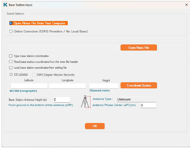
Click Import Base RINEX File
Choose a data source:
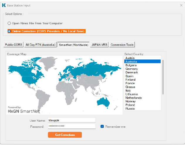
Open Rinex File From Your Computer Use this option to manually load RINEX files from a local directory.
Click Open Rinex File to browse to your base station data folder and select the desired file. Supported formats include:
• Standard RINEX files (*.o, *.obs)
• KlauPPK base station logs (*.ppk)
• UBX logs (*.UBX), and
• DJI BaseStation RTCM logs (*.DAT).
To select multiple files such as when your base station data spans several files, hold down the Ctrl or Shift key while selecting. Once your selection is complete, click Open to proceed.
After selecting the file:
Enter your base station coordinates and any other required fields. The software will automatically extract from the RINEX header the:
• Antenna height
• Antenna Phase Center (APC) position
You may manually edit these values if adjustments are needed.
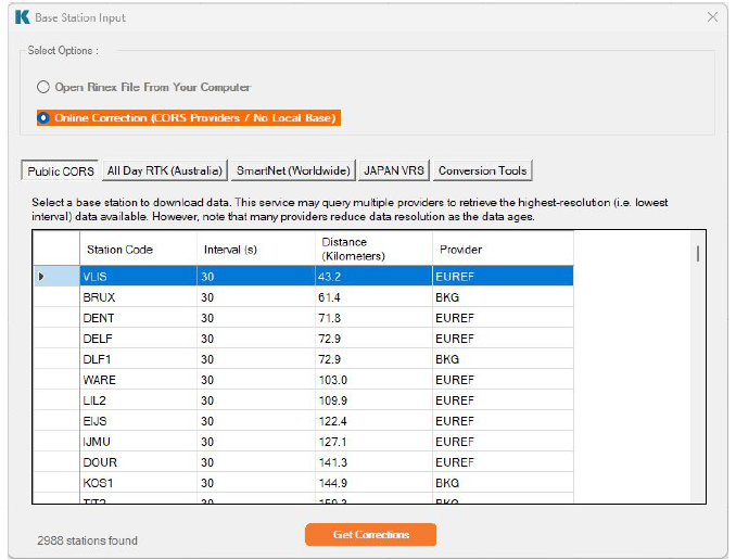
Online Corrections (CORS Providers / No Local Base)
If you’re unable to obtain “fixed” results in your processing or don’t have access to a local base station, there are several integrated online correction options available to enhance your solution.
Public CORS (No Account Needed)
This tool simplifies the retrieval of public CORS data by:
• Automatically locating nearby CORS stations
• Retrieving data that covers the entire observation period
• Selecting optimal data (based on sample interval)
• Falling back to alternate sources when needed and available
The system provides access to 3,754 Continuously Operating Reference Stations (CORS) across 81 countries, including major geodetic networks such as:
• NOAA (North America)
• Geoscience Australia
• BKG / IGS (Global)
• EUREF (Europe)
• GeoNet (New Zealand)
• IBGE (Brazil)
No login is required - ideal for quick access to widely available public stations. Continually Expanding Coverage - We are actively extending support for new regions and CORS stations to improve data availability and accuracy worldwide.
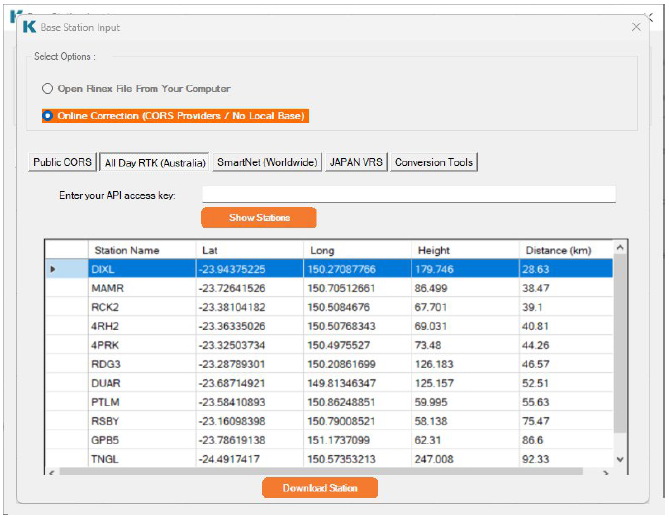
Premium CORS Services (Account Required)
These platforms offer more consistent access to high-quality correction data:
AllDayRTK: High-density CORS network supporting Australia and New Zealand
SmartNet Worldwide: Global coverage across many regions with premium-grade GNSS positioning
Access to these services requires an active account with the respective providers.
Conversion Tools
Additional utilities are included to support file compatibility:
• Compressed RINEX → Standard RINEX
• UBX → RINEX
These tools help ensure your files meet format requirements for post-processing or correction services in KlauPPK UAV.
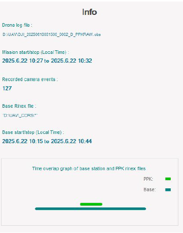
Once the base station data is selected/downloaded the right-hand side panel will show the local start and end time of the base data and the time overlap graph with your base station and drone data.
You will now be able to proceed with processing the GPS data.
Step 4: Process GPS Data
This step performs Post-Processed Kinematic (PPK) analysis on the GNSS data. Once initiated, the system will compute high-accuracy positions using reference base station corrections.
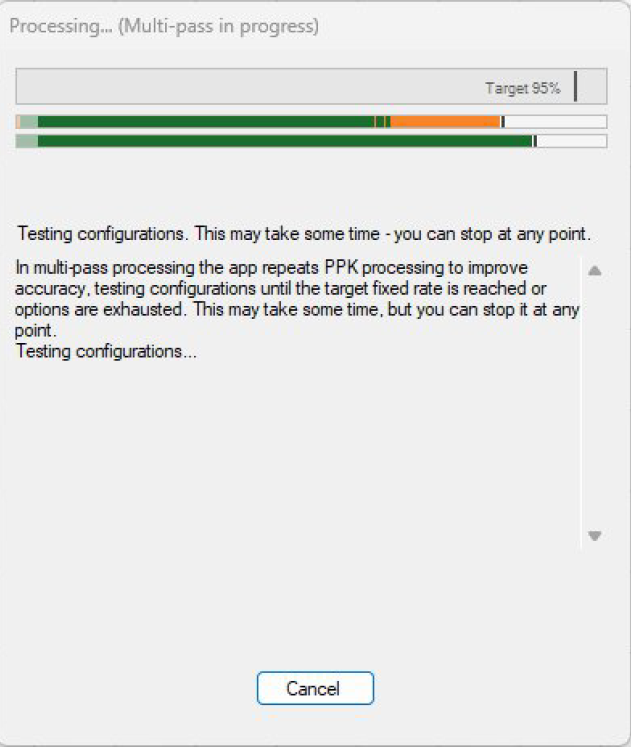
During processing, a dialog window displays the current progress percentage. If multi-pass processing is enabled and the fixed results ratio is below your configured target setting, the app will continue running additional concurrent PPK passes with different configurations until the target fixed rate is reached or all options are exhausted. You can cancel processing at any time by clicking the Cancel button.
Once processing is complete, the dialog window closes and the list of processed coordinates is displayed, confirming successful completion. Processing time depends on mission duration, baseline distance, data density (for example, 1‑second intervals may take longer), and the number of PPK passes required (if enabled) to reach the fixed result target.
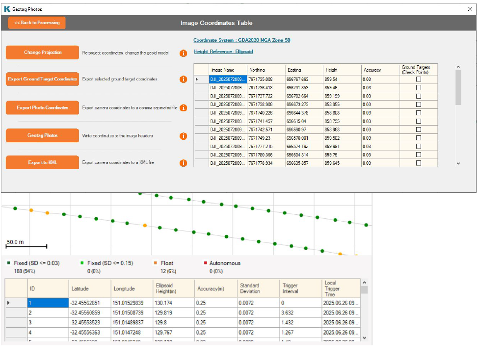
Each camera capture event is plotted on the grid and color-coded by its computed precision: dark green for centimeter-level (≈3 cm), bright green for sub-decimeter (≈15 cm), orange for float fixes, and red for autonomous solutions. The legend beneath the grid shows each color, along with the count and percentage of events in each category. You can pan, zoom in, and zoom out with your mouse to explore the data.
Clicking a marker opens its location details, where you’ll find coordinates and other metadata, plus a link to view the point directly in Google Maps. The same events are listed in the table below the grid. Clicking any row highlights and briefly pulses its corresponding point on the map for quick cross-reference.
Step 5: Open Image Folder
Select the image folder to import. A progress indicator will appear in the bottom-right corner, displaying the percentage of photos that have been read. This allows the system to assign post-processed GPS coordinates to each photo and link orientation data where available. Together, this ensures each image is accurately positioned and aligned in space.
From this window, you can update the coordinate system of your camera positions, define a local site coordinate system, set the height reference, and export the processed positions or geotag them directly into the image metadata.
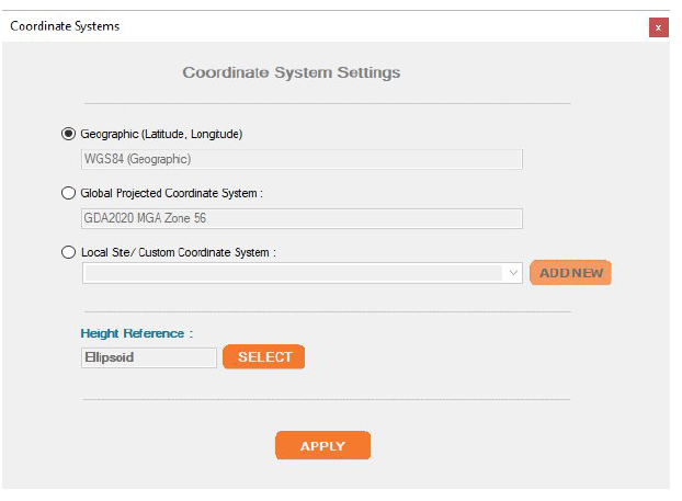
Changing the Coordinate System
Click Change Projection to select your preferred coordinate system and height reference. This defines how photo positions will be represented during export or geotagging.
Defining a Site Localisation (Custom Coordinate System)
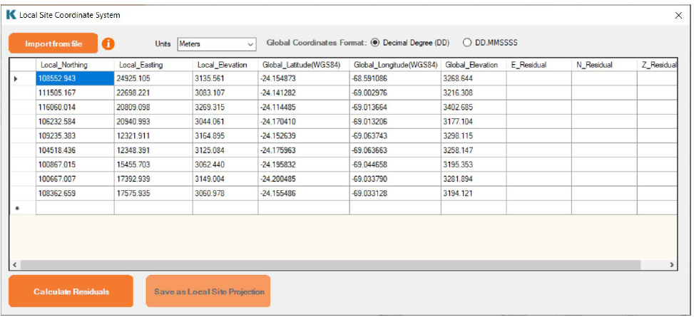
Commonly used in mining and construction environments, custom local coordinate systems can be defined by clicking Local Site/Custom Coordinate System, then selecting Add New.
To create a custom site localisation:
• Prepare a plain text file with at least five pairs of coordinates.
• Each row must include 6 space-separated columns:
• 3 columns for your local site coordinates
• 3 columns for geographic WGS84 coordinates
• The column order must match the format shown in the reference image above.
Once imported:
• Click Calculate Residuals to view transformation errors.
• If acceptable, click Save as Local Site Projection and assign a name.
• You can later select this saved system from the Local Site/Custom Coordinate System dropdown to
apply it to all photo positions.
Exporting or Geotagging
Once the coordinate system has been applied (if applicable) you can choose one of the following options for use in photogrammetry software:
• Geotag photos by embedding coordinates directly into the EXIF metadata.
Note: EXIF format only supports WGS84 latitude and longitude.
• Export a CSV or tab-delimited file containing photo filenames and accurate coordinates in your
preferred coordinate system.
• Export the camera coordinates to a KML file
Note: KML format only supports WGS84 latitude and longitude.
Make sure to match the reported accuracy field from your output to the camera accuracy settings in your photogrammetry workflow.
Multi-Flight Missions
KlauPPK UAV can process several related flights as a single mission - for example battery swap overs over one site, or surveys that span multiple take-offs. Each flight is optimised independently and in parallel using its own full multi-pass sequence, then the results are combined into one set of camera positions, one photo list and one export. Accuracy for each flight is identical to processing it on its own; a flight with poor data (such as heavy cycle slips) cannot affect the results of the other flights.
Importing Multiple Flights
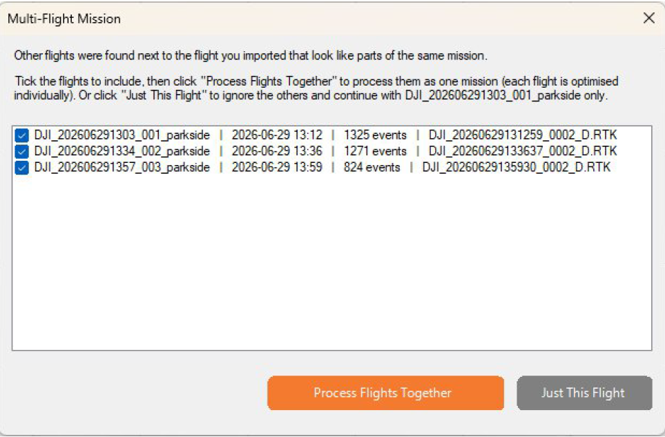
Import the first flight exactly as in Step 1: click Import Drone Log File and select the log from one of the flight folders. The software automatically looks in the neighbouring folders for related flight. Each candidate needs its own log and timestamp (.MRK) file and must have been flown on the same day. When related flights are found, a Multi-Flight Mission window lists them with their times and photo event counts.
• Tick the flights you want and click Process Flights Together to treat them as one mission.
• Click Just This Flight to ignore the others and continue with a normal single-flight workflow.
• You can also select several log files at once in the file dialog if they are stored in the same folder.
If a raw log (.rtk or .bin) is available alongside a selected .obs file, the usual recommendation to use the raw file appears once and applies to every flight in the mission. Flights must not overlap in time. Overlapping logs usually mean two drones were flying at once, which is not supported as one mission.
Note: In a multi-flight mission the timestamp files are read automatically from each flight folder, so Step 2 (Import Timestamp File) is not used and can not be changed.
Base Station and Multi-Flight Missions
Import the base station data as normal in Step 3. One base station covering the whole mission is typical; multiple base files are also supported. Before processing starts, the software checks that the base observations cover every flight individually and warns you if any flight has no coverage or only partial coverage. A flight without base coverage cannot be corrected and would produce low accuracy results. All the integrated CORS providers automatically request data spanning from the start of the first flight to the end of the last.
Processing a Multi-Flight Mission
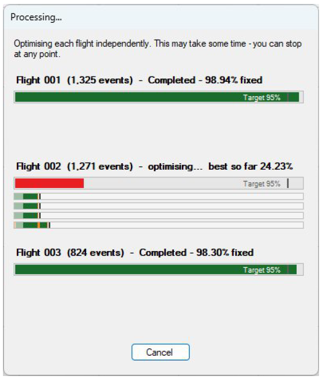
Click Process GPS Data as normal. The processing window shows one row per flight, each with its own progress bar and status log, because the flights are processed at the same time:
• The header above each bar shows the flight and its current activity, for example "Flight 004 (1,325 events) -
running Pass 2...".
• During processing the bar colour shows the current solution quality for that flight: green for fixed, orange for
float, red for autonomous.
• When a flight finishes, its header shows the final result and the bar colour becomes a verdict: green when
the flight met your target fixed rate, orange when it fell short, red when it achieved less than half the target.
• The status log under each bar records every completed pass for that flight.
If one flight fails to process, its row is marked FAILED and its photos fall back to the camera positions from the drone, while the remaining flights complete normally. Cancelling stops all processing.
Photos for Multi-Flight Missions
In Step 5, select the folder that contains all flights’ photos - photos in subfolders are included automatically, so you can keep each flight’s photos in its own folder and simply select their parent folder. The folder dialog opens at the mission folder by default. Copying all photos into a single folder works equally well.
Photo name conflicts:
Some drones (for example the Phantom 4 RTK) name photos with a simple counter that can repeat between flights, especially if the memory card was formatted between flights or the counter passed 9999. Photo names must be unique across the mission for geotagging and photogrammetry software, so when the software detects the same filename in different flight folders it offers to fix this automatically: every photo in the affected folders is renamed with its flight prefix (for example 004_DJI_0001.JPG), and a list of the renames is saved to photo_renames.csv in the mission folder. Click Cancel instead if you prefer to resolve the names yourself. Identical duplicate copies of the same photo are ignored rather than renamed.
Results and Outputs
After processing, the coordinate list, map and photo grid contain every flight’s events in time order, and geotagging and exports work exactly as for a single flight.
Notes and Limitations
• Multi-flight missions are intended for related flights: the same drone and site, typically the same day.
• Each flight folder must contain its own timestamp (.MRK) file alongside the log.
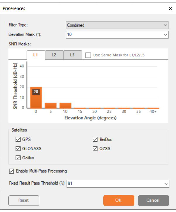
PPK Preferences
The Preferences window allows you to:
• Set signal filtering parameters
• Define elevation and SNR masks
• Select satellite constellations
• Enable multi-pass processing
• Adjust fixed result pass thresholds
Filter Type
Combined:
Description: Runs both forward and backward passes through the GNSS data, then merges the results. Benefits: Offers the most robust solution, especially in areas with signal loss or multipath interference. Use Case: Ideal for high-precision applications like surveying, mapping, or photogrammetry where consistency and reliability are critical
Forward Only
Description: Processes data chronologically from start to finish. Benefits: Faster and simpler, but may struggle with signal dropouts or poor satellite geometry. Use Case: Suitable for real time emulation or when backward data isn’t available.
Backward Only
Description: Processes data in reverse; from end to start.
Benefits: Can improve results in scenarios where the end of the dataset has better satellite visibility. Use Case: Useful for post-processing when the forward pass yields poor results due to early signal issues.
Elevation Mask (°)
Description: Sets the minimum elevation angle for satellite inclusion. Benefits: Exclude low elevation satellites, reducing multipath errors. Use Case: Helpful when you are getting float solutions from low angle satellites that degrade fix quality. Raising the mask forces the processor to rely on higher elevation satellites, which typically provide stronger, cleaner signals and improve the chance of achieving a stable fixed solution.
SNR Mask Configuration
Description: Defines the minimum signal-to-noise ratio (SNR, measured in dBHz) required for satellites to be included in processing. Thresholds can be set by elevation angle, and optionally applied equally across L1, L2 and L5 bands. Benefits: Filters out weak or noisy signals that can cause cycle slips, float solutions, or degraded accuracy. Ensures only satellites with sufficient signal strength contribute to the solution. Use Case: Helpful when you are getting unstable fixes due to low quality signals, especially in environments with interference, multipath, or partial obstructions. Raising the SNR mask excludes marginal satellites, improving reliability of fixed solutions. Tip: Use Same Mask for L1/L2/L5 applies the same SNR mask to the L1, L2 and L5 bands.You can adjust the values by dragging the bars up and down.
Satellite System Selection
Choose which GNSS constellations to include in processing:
• GPS
• GLONASS
• Galileo
• BeiDou
• QZSS
All systems are enabled by default for maximum coverage.
Multi-Pass Processing
Description: Runs multiple passes of the GNSS data through the processing engine, comparing results across iterations to refine accuracy. Benefits: Helps automate the detection and rejection of false fixes caused by noise, multipath, or poor satellite geometry. Use Case: Helpful when you are getting inconsistent fixes or frequent float solutions.
Fixed Result Pass Threshold (%)
Description: Sets the minimum fixed result ratio that a single processing pass must achieve for its results to be accepted. Once a pass meets or exceeds this threshold, multi-pass processing stops and the solution is finalised. Benefits: Prevents unnecessary additional passes once a sufficiently strong fixed solution is found, saving time while ensuring reliability. Use Case: Helpful when you want to enforce a minimum quality requirement for accepting a pass as the final result. For example, setting the threshold to 95% ensures that only passes with at least 95% fixed epochs are accepted, and once such a pass is found, its results are used.
To revert the preferences back to the the default settings, click the reset button on the bottom left of the preferences window.




Process your next flight with KlauPPK
Start a 14 day, full-function trial and test KlauPPK with your own project data. No credit card required.